Live TV

skip to main content Hindi

       RESEARCH DEPARTMENT

ALL INDIA RADIO & DOORDARSHAN

     R&D        Rem.Mon.       Labs        Monetization        Publications        Photo  Gallery


TELEMETRY LAB


The Web based Telemetry system has been implemented at following AIR stations:

FM Transmitters: Kailashahar,Kasauli,Nagaur,Cuttack,Satara,Hazaribagh, Jalandhar & Pune.

Field trial of Remote Monitoring for 100W AIR FM transmitter is being carried out at Ambala.

MW Transmitters: Leh,Rohtak,Chhatarpur,Jalgaon,Tirunelveli, Brahmavar, Silchar,Thiruvanathapuram,Tura,Aizawl, Rewa,Ambikapur,Bhuj, Darbhanga & Ratnagiri.

Status of transmitters can be seen presently via Click either on table or on the map above:
(user name and password is on tooltip of click)


TELEMETRY LAB


Web-based Remote Monitoring & Control System

Research Department of All India Radio and Doordarshan has developed a Web-based Remote Monitoring & Control System for AIR FM/MW transmitters. The status of AIR transmitters can be monitored from a remote location on mobile phone/tab/laptop/desktop etc.

Implementation:

The Web-based Remote Monitoring System has been successfully installed and commissioned in AIR MW/FM Transmitters of Rohtak, Chhatarpur, Tirunelveli, Ambikapur, Brahmavar, Bhuj, Ratnagiri, Aizawl, Tura, Trivandrum, Jalgaon, Silchar, Leh, Rewa and Darbhanga. Nagaur, Kailashahar, Jalandhar, Kasauli, Satara, Hazaribagh, Pune and Cuttack.

Facilities:

  • This system can be used for FM/MW transmitters.
  • It is Cost effective, in house designed & developed.
  • Transmitter and its auxiliaries can be operated and monitored from any location through mobile or desktop.
  • It helps in analysis of the operation of the transmitter and other auxiliary equipment installed at the transmitter.
  • Monitoring of Modulation index, Temperature, Humidity and smoke detection of Transmitter hall.
  • Provides smoke detection and fault indication with alarm.
  • System automatically stores all the analog and binary (status) parameters, which can be used for periodic report generation.
  • The system will provide extensive support to the technical staff in operation and maintenance of the transmitter.

TELEMETRY LAB


Web Based Centralized Monitoring System for MW/FM Transmitters

MW/FM transmitters of All India Radio have been installed at different locations of India .To monitor these transmitters by five zonal offices is very difficult. The Research Department of All India Radio & Doordarshan has developed a Web based centralized monitoring system for remote monitoring of MW & FM transmitters and its auxiliaries. It stores and displays all parameters (binary as well as analog) of transmitter and its auxiliaries.

Introduction:

Transmitters installed at different locations of India communicates to database server via communication link from the server kept at stations. SCU provides parameters of transmitter to server and server then sends all the parameters to database server via communication link.

Fig.1 Block Diagram of Control Unit Setup

System Description:

Centralized Monitoring system is connected to all transmitters through IP network. Server of station sends data to the centralized monitoring system through predefined link on IP network. This data is stored in SQL data base.

Centralized Monitoring system GUI is linked to all transmitters which appear on screen with running power, modulation index and color (red or green) indicators. If red color appears in front of particular transmitter then it means transmitter is running below certain level of power or modulation index. If there is green color then it means transmitter is running properly.

If there is any fault at any station then we have to click that particular station link and we will find all parameters of transmitter in detail for further analysis.

Application Software:

The data base will acquire, and store the data in data base on hard disk automatically for retrieval and analysis.

  • Displaying the transmitter parameters through IP network.
  • Displaying the transmitter status with power, modulation index, color and station link on the computer/mobile screen.

The Monitoring GUI that will appear on the computer /Mobile screen

GUI of main screen in which all the zones are listed.

Zone wise parameter details of transmitters.

Station wise parameter details of transmitter

Low power details of all transmitters in zone

Report for low power of transmitters in zone.


TELEMETRY LAB


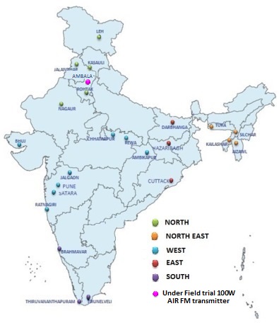
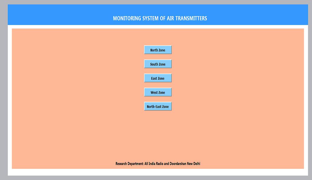
Auto Control and Monitoring system of 100W FM Transmitter

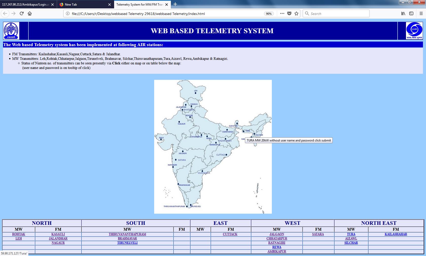
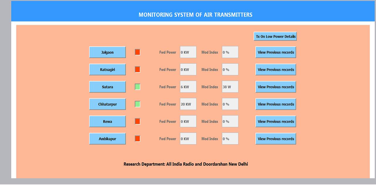
Control unit is developed for the remote monitoring and controlling of 100 watt FM transmitter. Initially when FM transmitter is operating smoothly, the control unit will monitor all the parameters (binary, analog and auxillary) and display them in graphical user interface (GUI) hosted in web server. Whenever some fault occurrs or in case of any other event causing non operation of primary transmitter then control unit will issue necessary commands in order to change transmitter from primary to standby transmitter along with parameters related to standby transmitter. Beside this, control unit will also send email regarding non-functioning of transmitter to the concerned officer for further action. System is providing real time transmitted audio stream.

System Description:

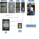
Control Unit which is installed at the transmitter end, mainly consist of Arduino board based on a 32-bit ARM core Microcontroller, Relay interface board and Power supply. Fig1 shows the block diagram of control unit setup.

Fig.1 Block Diagram of Control Unit Setup

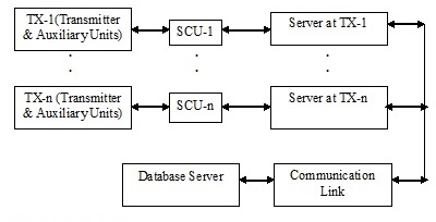
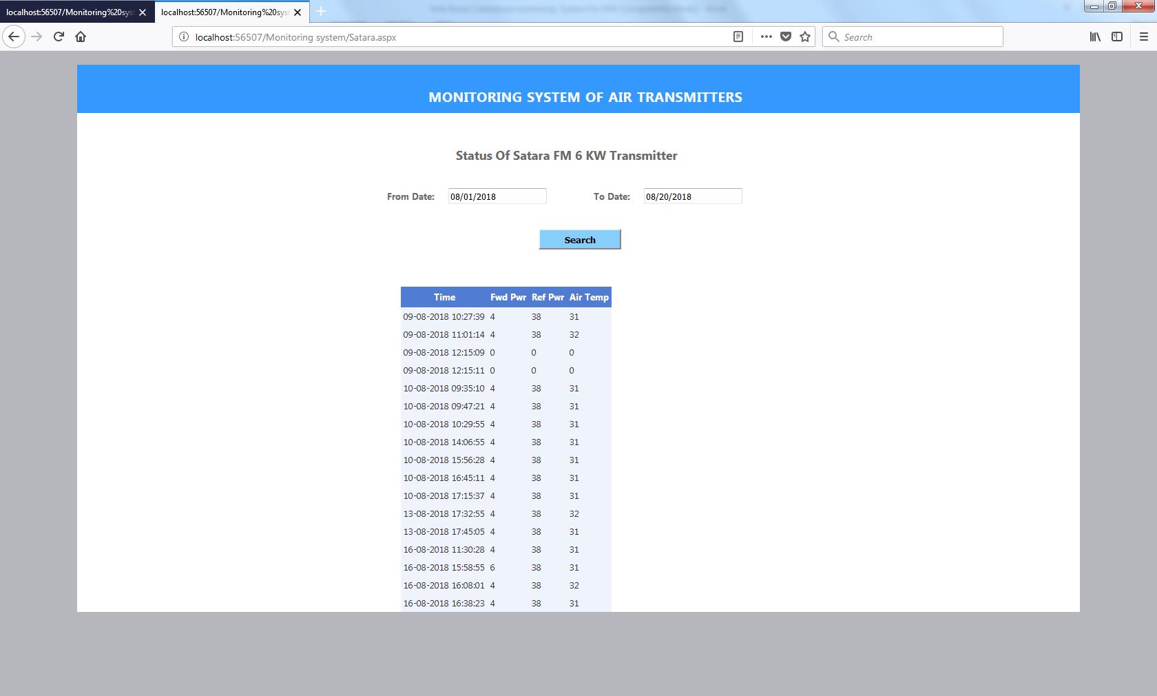
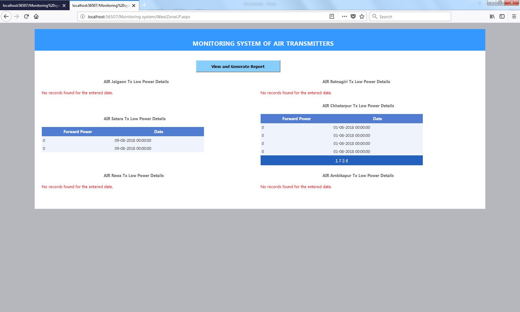
The transmitter’s both analog and binary parameters are connected to the control unit. The control command is given to the transmitter through the relay by controller itself. Initially both the transmitters (primary and standby) should be in local mode. If primary transmitter fails or forward power is less than 50 Watt then the control unit will issue the switch off command for the primary transmitter, and simultaneously changes the RF switch in position to standby transmitter and switches on the standby transmitter. If standby transmitter also fails, then controller sends the email and SMS to the controlling officer and switches off the power supply of the transmitter unit. Relay and Arduino board are operated through 5 volt dc for its operation. Status of external parameters like humidity, temperature, phase voltage are fed to the controller through the transducers. The transmitter data is displayed on computer monitor/ mobile screen and the same is stored in database running in the back end. The web page GUI (Fig.2) periodically accesses the transmitter data through internet.

Fig.2 Block Diagram of Control Unit Setup

Data communication between the transmitter and control unit is through the serial port (COM) of computer. Further improvement can be introduced by providing ethernet shield board connection to the Arduino board for data transfer and data storage to the server.

Fig.1 Block Diagram of Control Unit Setup


TELEMETRY LAB


The Web based Telemetry system has been implemented at following AIR stations:

FM Transmitters: Kailashahar,Kasauli,Nagaur,Cuttack,Satara,Hazaribagh, Jalandhar & Pune.

Field trial of Remote Monitoring for 100W AIR FM transmitter is being carried out at Ambala.

MW Transmitters: Leh,Rohtak,Chhatarpur,Jalgaon,Tirunelveli, Brahmavar, Silchar,Thiruvanathapuram,Tura,Aizawl, Rewa,Ambikapur,Bhuj, Darbhanga & Ratnagiri.

Status of transmitters can be seen presently via Click either on table or on the map above:
(user name and password is on tooltip of click)